|
XTRAC Process Designer User Guide |
|

|

Intermediate and Boundary Event Shapes
Intermediate events define actions taken during a process flow, such as a delay, listening for a signal, sending messages, and escalation.
A boundary event is a catching intermediate event drawn on the boundary of a task or activity. It means that while a task is running, the process listens for a signal. If an intermediate event occurs before the task completes, the sequence flow (the exception flow) out of the event is triggered. On the other hand, if the task completes without the occurrence of the boundary event signal, the exception flow is ignored and the process continues on the sequence flow out of the activity called the normal flow.
A boundary event is created by dragging a boundary event shape over a shape that has already been placed on the canvas. Each shape that accepts boundary events has eight anchor points. Drop a boundary event shape on an anchor point.

Timer
The timer shape is represented as a stop watch in an orange circle.

An intermediate timer event acts as a delay in the sequence flow. The timer can be configured to wait for a specified duration or until a specified date and time. You can use these timer events to model exceptions, delays, and deadlines.
Timer Event Configuration
Use the Timer Event Configuration dialog to configure how long a delay will last before the process can continue.
| 1. | Open the Timer Event Configuration dialog using one of the following ways: |
- Right-click a timer event shape and select Configure Timer Event.
- In the Intermediate Timer Event Properties panel, click the Timer tab, and then click Configure.
| 2. | In the Timer Event Configuration dialog, select Business Days or Calendar Days. |
| 3. | Select a delay option: |
- Delay for a fixed duration
- Click the up-down controls to set days, hours and minutes or enter numbers in the boxes.
- Note: One day is 24 hours, If business calendar is selected, the timer counts down for business days only and uses business calendar time zones.
- Delay until a specific time
- Click the up-down controls to set the hour, minutes or enter numbers in the boxes. Select AM or PM and the time zone.
- Note: If Business Days is selected, time zone selection is disabled. It is configured with Business Calendar.
- Timer variable
- Select a datetime data object from the Timer Variable Data Object list.
| 4. | Click Save. |
The timer event's configuration parameters are added to the Timer tab in the Intermediate Timer Event Properties panel.
Timer Interrupting and Non-interrupting Boundary Events
A timer interrupting boundary event is represented as a stop watch in a circle that has been placed on the boundary of another shape.

When a timer interrupting boundary event is triggered, the task it is attached to is stopped and an alternate sequence flow is started.
A timer non-interrupting boundary event is represented as a stop watch in a dotted line circle that has been placed on the boundary of another shape.

When this type of event is triggered, the associated task continues and an alternate sequence flow is started.
A timer interrupting boundary event acts as a time out for an activity. The timer can be configured to wait for a specified duration or until a specified date and time. An alternate sequence flow is started if the timer expires.
Timer Interrupting Boundary Event Configuration
Use the Timer Event Configuration dialog to configure how long a delay will last before the process can continue.
For more information, see Timer Event Configuration.
Intermediate Signal Catch
The signal catch shape is represented as an empty orange triangle in an orange circle.

A signal catch listens for a signal throw event. The signal throw and signal catch are used as another way to pass data from process to process within the same model.
When you draw your diagram, you need to draw it so that the signal catch is listening for a signal throw before the signal is thrown. This ensures that the signal catch can catch the data from the throw.
If you have a signal throw with no signal catch, or a signal catch with no signal throw, the data will not be passed properly and the process will not complete when it is executed.
Intermediate Signal Catch Event Properties
Use the Intermediate Signal Catch Event Properties panel to define a signal catch event. The properties panel is available when you select a signal catch shape on the drawing canvas.
To open the Signal Catch Event Properties panel:
| 1. | Select a signal catch shape on the drawing canvas. |
| 2. | Click the Intermediate Signal Catch Event Properties tab below the canvas to open the properties panel. |
On the General tab, you can change the shape's name, add a description, and add a related signal throw.
| 1. | On the General tab, click Search next to the Add a Related Throw field. |
| 2. | In the Select Signal Throw dialog, select an existing signal throw from the list and click OK. |
On the Signal tab, associate the data output types.
| 1. | Select a signal catch shape on the drawing canvas. |
| 2. | Click the Signal tab. |
Note: The Signal tab is not available if you have not added data to the process model, and if you have not added a related signal throw to the signal catch.
The Signal tab displays data that has been associated with the related signal throw.
| 3. | In the Signal tab, click a data type and then click Associate. |
| 4. | In the Add Output Association, select the association type that matches the data output and click OK. |
After you have run a validation check on the process, the Validation tab displays any warnings or configuration errors associated with the signal catch event. Use these warnings to determine what needs to be fixed in order to validate the process. For more information, see Validating a Process Model.
Intermediate Signal Throw
The signal throw shape is represented as a solid orange triangle in an orange circle:

A signal throw is an intermediate event that is used to send a signal to a signal catch within the same process. The signal catch is configured to "listen" for signal throw events. The signal throw and signal catch are used as another way to pass data from process to process within the same model.
When you draw your diagram, you need to draw it so that the signal catch is listening for a signal throw before the signal is thrown. This ensures that the signal catch can catch the data from the throw.
If you have a signal throw with no signal catch, or a signal catch with no signal throw, the data will not be passed properly and the process will not complete when it is executed.
Intermediate Signal Throw Properties
To open the Intermediate Signal Throw Properties panel:
| 1. | Select a signal throw shape on the drawing canvas. |
| 2. | Click the Intermediate Signal Throw Properties tab below the canvas. |
On the Signal tab, associate the data output types:
| 1. | In the Intermediate Signal Throw Properties panel, click the Signal tab. |
Note: The Signal tab is not available if you have not added data to the process model.
| 2. | In the Signal tab, from the Data Dictionary panel or the Process Data panel, click and drag a data type to a row below the Input Name field. |
| 3. | In the Signal tab, click Associate. |
| 4. | In the Add Output Association, select the association type that matches the data output and click OK. |
Error Boundary Event
An error boundary event is represented by a lightning bolt in a circle that has been placed on the boundary of a service task shape:

When an error boundary event is triggered, the service task is stopped and an alternate sequence flow is started.
It is best practice to pair an error boundary event with a service task in case a service is not available. An exception handling path can notify you of a problem.
Error Interrupting Boundary Event Properties
To open the Error Interrupting Boundary Event Properties panel:
| 1. | Select an error boundary event shape on the drawing canvas. |
| 2. | Click the Error Interrupting Boundary Event Properties tab below the canvas. |
On the Error tab, associate data output types:
| 1. | In the Error Interrupting Boundary Event Properties panel, click the Error tab. |
| 2. | In the Error tab, from the Data Dictionary panel or the Process Data panel, click and drag a data type to a row below the Data field. |
| 3. | In the Error tab, click Associate. |
| 4. | In the Add Output Association, select the association type that matches the data output and click OK. |
Escalation Boundary Events (interrupting and non-interrupting)
An escalation interrupting boundary event is represented by an arrow in a circle that has been placed on the boundary of a user task shape:

When this type of event is triggered, the user task is stopped and an alternate sequence flow is started.
An escalation non-interrupting boundary event is represented as an arrow surrounded by a dotted circle that has been placed on the boundary of user task shape.

When an escalation non-interrupting boundary shape is triggered, the user task continues and a parallel sequence flow is started.
Escalation Boundary Event Properties (interrupting and non-interrupting)
Use the Escalation Boundary Event Properties panel to associate data outputs and to configure Business Data Mapping.
To open the Escalation Boundary Event Properties panel:
| 1. | Select an escalation interrupting shape on the drawing canvas. |
| 2. | Click the Escalating Boundary Event Properties tab below the canvas. |
On the Escalation tab, associate data output types.
| 1. | In the Escalation Boundary Event Properties panel, click the Escalation tab. |
| 2. | Drag and drop a data type from the Data Dictionary panel to a row below the Data field. |
| 3. | Select a row in the Data field and click Associate. |
| 4. | In the Add Output Association, select the association type that matches the data output and click OK. |
On the Business Data Mapping tab, associate XTRAC Process fields to XTRAC Workflow fields.
Configure Business Data Mappings
Business data mapping associates process data objects with workflow fields. If the data object name matches a workflow field name, the data and workflow fields are matched automatically.
| 1. | On the drawing canvas, select an escalation interrupting or non-interrupting boundary event shape. |
| 2. | In the properties panel, click Business Data Mapping. |
The grid displays two columns for Process fields and two columns for Workflow fields. The Process fields must be mapped to an XTRAC Workflow field equivalent.
| 3. | Click Configure. |
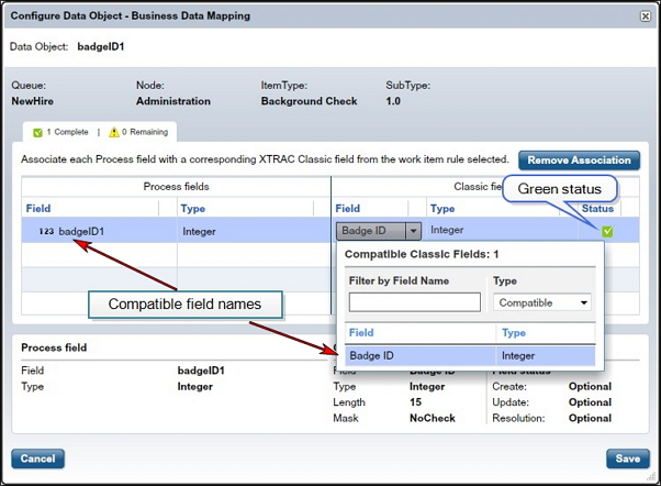
The Business Data Mapping dialog opens.
| 4. | From the Field column in the Workflow fields section, click the Select drop-down list. |
A list of compatible Workflow fields is displayed. If there are no compatible fields available from the XTRAC Workflow environment, this list will be empty. If there is a long list of available compatible fields, you can filter the results by entering all or part of the field name in the Filter by Field Name text box.
| 5. | Select a compatible field name from the list. |
The field name is mapped to the Process field and the status is changed from yellow to green as shown in the following example.
| 6. | Click Save. |
Repeat these steps for every data object associated with the process.
Note: Party data is mapped automatically to XTRAC Workflow fields when the data object name in the Data Dictionary matches the party data name in Workflow.
Message Catch
The message catch shape is represented as an empty orange envelope inside an orange circle:

This shape is a catching intermediate event, it is drawn with sequence flow in and sequence flow out, and means that the process waits for the trigger signal. When the trigger signal arrives, the process resumes on the sequence flow out of the event. A process can wait for a message or timer signal, but it cannot wait for an error.
Note: This shape is not executable in this release.
Message Throw
The message throw shape is represented as a solid orange envelope inside an orange circle.

This shape is a throwing intermediate event, and means an message signal is thrown as soon as the incoming sequence flow arrives, and the process continues immediately afterward on the sequence flow out of the throwing event. A Message intermediate event supports throwing behavior, but not Timer or Error.
Note: This shape is not executable in this release.
Escalation Throw
The escalation throw shape is represented as an orange arrow inside an orange circle.

This shape is a throwing intermediate event, and means an escalation signal is thrown as soon as the incoming sequence flow arrives, and the process continues immediately afterward on the sequence flow out of the throwing event.
Note: This shape is not executable in this release.
XTRAC Community |

|